Octa-Geodesic Dome
Building a 2-metre Octa-Geodesic Dome
by Eric W. Walker 
- Considerations
- Options and limitations
- Design
- Construction of plinth and pier
- Construction of side frame, and dome base and rail
- Construction of sides, door and watershed
- Construction of Geodesic dome
- Inside the dome, and summary
Considerations
Why bother to build?
- Scottish Highlands weather - enough said !
- Minimise affects from light pollution - especially security lighting !
- Astrophotography - can take 60-90 minutes to set up equipment and accurately polar align
- "Organised" observing - all equipment, observing aids, laptop, notebooks, maps at hand
- Cheaper than purchasing "off-the-shelf" observatory - £2,000 to £3,000 for ready-made, delivered, and installed
What do I want to achieve?
- Protection from the elements
- can observe in light winds
- easy shut-down / start-up in e.g. rain showers
- minimise / eliminate dewing - Shaded from light pollution
- especially security lighting ! - Permanent set-up
- always accurately polar-aligned
- "ready to go" / ready for imaging in <30 minutes - "Organised" observing
- all equipment, observing aids, laptop, notebooks, maps at hand
- power, internet access - Environmental considerations
- maximise renewable / recycled materials
- minimise petrochemical derived materials - Security
- Minimal cost
- £400 - £600
Options & limitations
- Shed with roll-off roof
- light pollution / dewing? - Rotating dome
- spherical / hemispherical vs. geodesic
- square base vs. polygonal base - My skills and equipment
- no workshop and limited toolkit
- never built anything this scale / complexity - Time
- after work & weekends ..... but not every spare moment !!!
- spring through summer, ready for autumn observing - Appearance
- significant input from my wife ! - Minimal cost
- £400 - £600
Design
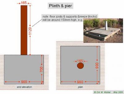
I decided on a wooden plinth because it was readily available, is renewable, and would easily cope with the weight and dynamics of my 8" Meade SCT. Note that the final height of the plinth is decided by the actual dimensions of your base floor and preferred observing height, etc.
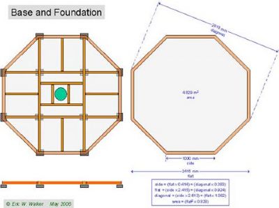
My wife insisted that the observatory mustn’t look like a boxy wooden shack at the bottom of the garden so she "suggested" an octagonal design would serve the purpose. This base turned out to be an ideal and stable support structure. Make sure you include all the bracing / joists as indicated to support and distribute your weight across the floor. I have included the fundamental dimensions and their arithmetic relationships in order to evaluate various size options.
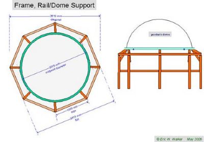
This simple frame and bracing structure design turned out very firm and stable. I didn't need the "cantilever" upper braces for the dome rail as the 3"x2"s with 8mm carriage bolts and PVA wood glue was so solid.
I also decided to build a geodesic dome and found the following websites indispensible for basic dimensioning and construction advice from which I developed my own ideas and techniques.
http://www.desertdomes.com/rev3calc.html
http://www.orednet.org/~jgarlitz/geodome.htm
http://obs.nineplanets.org/obs/obslist.html
Construction of Plinth and Pier
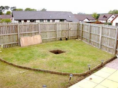
Every journey starts with the first step ........ or shovel! Little did I know how much work was ahead of me. I should have got a big clue from this starting point of digging a hole (900 x 900 x 700mm) on 14 May 2005.
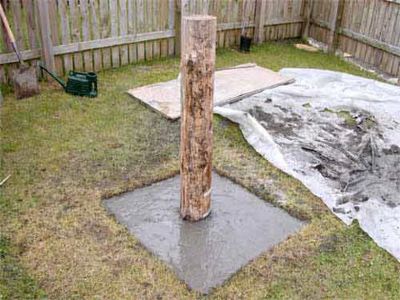
I used a 2.1 metre length of timber which was originally destined to be sawn and chopped up for firewood. It has made an excellent and stable plinth for the 8" Meade SCT.
The plinth was formed from 0.6 cubic metres of hand-mixed concrete (sand:aggregate:cement 1:1:1). A big tip - use a cement mixer! This took over six hours to complete and was real back-breaking hard work. Another four days for the concrete base to cure and the entire plinth & pier assembly was permanently in place. No going back now!
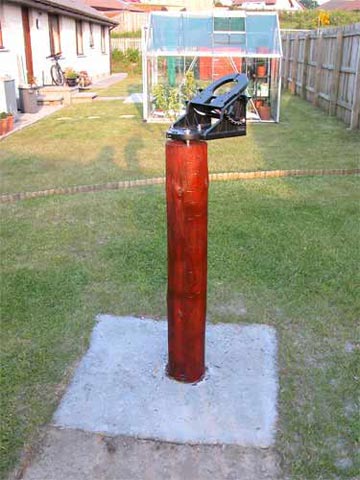
I used threaded rod screwed about 6cm into the timber pier and fixed securely with a nut and washer. The telescope wedge is mounted on top of a nut & washer assembly which facilitates fine levelling adjustment.
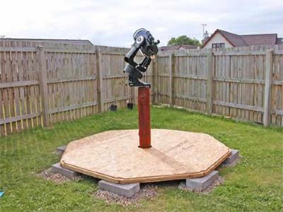
A look at the finished plinth, pier, and levelling assembly with wedge attached.
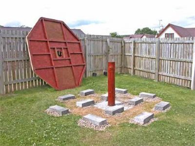
My dear lady wife insisted that the observatory would not be a "square wooden shack messing up the garden" and she "suggested" the octagon - bear in mind I have never built anything like this before! I used 3" x 2"s for the outside of the base and 2" x 2"s for the internals. The pieces were securely screwed together with a mixture of 2" and 1.5" woodscrews.
My garden is composed of firm clay and the breeze block foundation was more than adequate. The blocks were levelled and the base laid on top. Note that I subsequently added more supporting joists to the base, as per the original plan, to give it more support.
The base and plinth with the mount and scope fitted - just to get a feel of how it would eventually turn out. I was able to use it as an observation platform at this stage. Note that there is a gap between the plinth and the hole in the base so that no vibrations would be transmitted to the plinth while walking around.
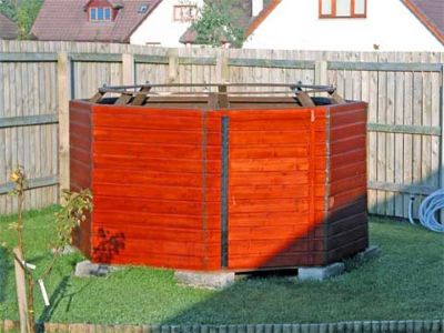
Construction of Side Frame, and Dome Base & Rail
It's amazing the combined strength of 3"x2"s, 2"x2"s, 4" carriage screws (top and bottom of uprights), 2" woodscrews (all other joints), and, of course, that wonderful stuff ..... PVA wood adhesive.
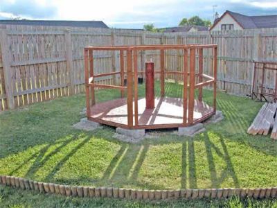
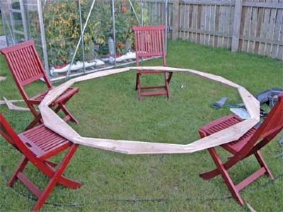
I had to calculate the internal and external dimensions of the octagonal "rings" for constructing both the dome base and supporting rail in order that the dome fitted securely.
Each side of the base octagonal was joined using a combination of two wooden dowels, staples, and ..... yes, you've guessed it ..... PVA wood adhesive. I worked out in advance that I would need to further trim the rail to ensure clearance of the dome skirt which would eventually be fitted. In fact, I had to trim a further centimetre or so off eight of the corners (making a sixteen-sided figure) once the dome was placed on the rail casters to get the right clearance - not a difficult job though!
3"x2" wooden braces attached to each upright using 8mm diameter carriage bolts and ..... PVA wood adhesive. An extremely strong combination and I didn't have to add the "cantilever" braces I thought I might have to in the original plans. The dome rail was checked for level and attached with two 4cm woodscrews at each support.
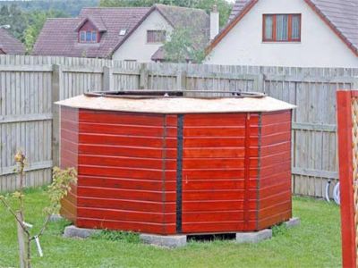
Construction of Sides, Door, and Watershed
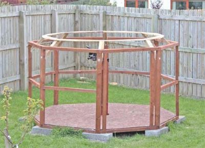
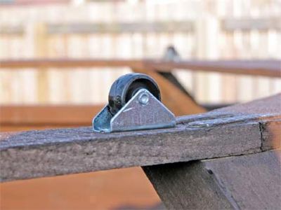
The outside "skin" for the frame and door was constructed from shiplap. Once the door was on and painted the joints were silicone-sealed and the rail casters fitted.
Initially I attached the casters to the base using small woodscrews but I later replaced them with nuts & bolts and raised the height a couple of millimetres off the base using washers. This ensured the dome skirt cleared the roofing shingles attached to the "watershed" (see below) and provided a much more secure fixing.
The watershed was constructed using eight cut-to-shape segments of OSB board.
Construction of Geodesic dome
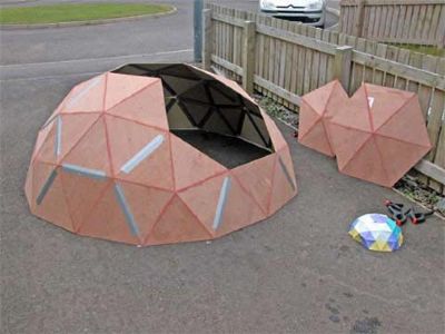
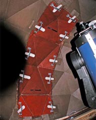
75 triangles of the correct dimensions were cut out of 5mm plywood sheeting. They were glued together using Pink Grip grab adhesive into combinations of pentagons, hexagons, and half-hexagons.
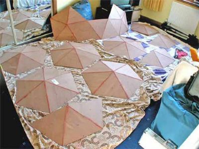
This was the exciting part - would all the pieces fit together and make the desired dome shape? The individual shapes were "tacked" together using duct tape then glued with Pink Grip. This job required two people and also some spring clamps to hold things together during assembly. One of us had to enter the dome and work inside while the other glued the final pieces from the outside.
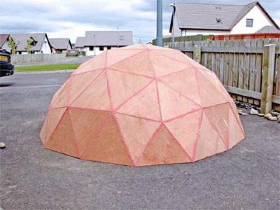
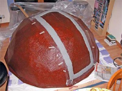
The dome was covered with plastic sheeting for a week to protect it from the weather and let the Pink Grip adhesive cure and form a strong bond.
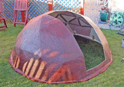
The dome frame was covered with a layer of papier-mâché (shredded newspaper, hand-pulped in a mixture of 1:10 PVA adhesive:water). 60-70 litres of papier-mâché was needed. The dome took ages to dry as the weather turned cooler and cloudy and I was concerned it would turn mouldy. I had to cover it with a tent made from the upper part of a cheap gazebo and sides formed using plastic dust sheeting. I used a 2kW fan heater on and off for a week to assist the drying process.
The dome was painted with two coats of red mahogany satin finish wood preserver.
The papier-mache formed a good bond with the plywood frame. The dome was securely attached to the dome base ring by wedge-shaped blocks of wood screwed and glued to both the base and frame.
The frame was also glued all the way round with another strong grab adhesive which cured over a period of days. I cut out a 50cm wide hatch and extended past the top centre point of the dome to ensure I could observe the zenith when the observatory was finished.
The cut out piece would be used to make the observatory hatch lid.
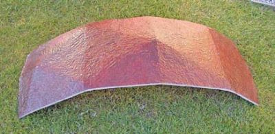
The weather was turning against us and we had to take the dome assembly indoors in order to add a papier-mâché weather-tight lip to the hatch. Note the "cling-film" to prevent the papier-mâché adhering to the dome surface.
 In order to keep the dome running on track I attached a skirt made of 6mm rubber compound. It is quite stiff but with enough flex to "ride" the guide rollers. It was screwed on using 4cm "easy fixings" (for chipboard & plasterboard) and the tops later painted with black enamel paint for cosmetic purposes. The dome was further weather-proofed with two coats of yacht varnish.
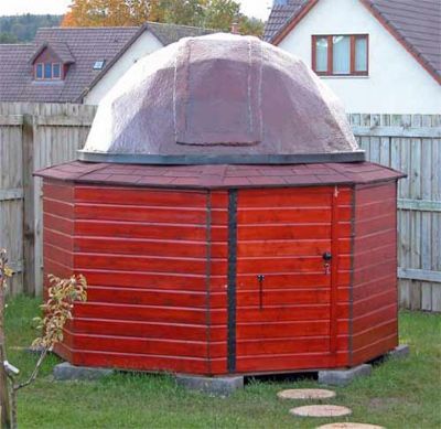
Roofing shingles were attached to the watershed and the whole assembly sealed with silicone sealant ensured a pleasing appearance and a functionally weather and watertight structure.
Hatch off and stowed inside, scope up and ready for viewing after five months work - a really great feeling!

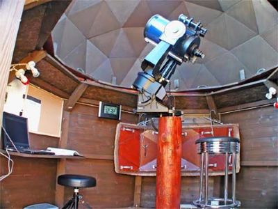
Inside the Dome
The hatch is very easy to open by angling it then taking it inside the dome and simply reversing the operation to re-attach it. The thin rubber weather seal on the inside surface of the lip and the door-stop wedges between the support blocks and adjacent handles ensure a weather and watertight seal.
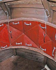
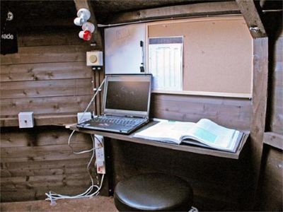
The working area of the dome is quite spacious and the image below shows how it is all laid out. There is a workstation with foldaway shelf, whiteboard and pinboard for skymaps, notes, data, etc., and an adjustable height stool for use either at the workstation or scope. The laptop is plugged into my home network and internet via an ethernet socket. You can see the red-white changeover lighting at opposite sides of the observatory. The hatch fits snugly against the inside base wall so I devised a simple way of stowing it by hanging it on two S-hooks suspended from two of the dome support braces. It prevents the hatch being damaged, is easy to attach and remove, and doesn't present a tripping hazard when observing. A radio-controlled clock is tuned into the Greenwich signal and the internal temperature is also displayed. The handles to assist with rotating the dome can be seen on the dome base ring. In addition to the generous floor space you can see that there is also plenty of headroom.
The following image shows the foldaway worktop & shelving, thermostat for controlling internal temperature via 120W tube heater or 700W oil-filled heater (frost & moisture protection - 700W heater required for very cold periods), red-white changeover lighting (on-off-on switch at left of image), ethernet socket (slightly hidden by shelf & laptop), 240V 13A mains socket outlet. Not shown is a local alarm system which was amazingly easy to link into the house alarm system.
Summary
This has been a very successful and satisfying project. All my original objectives were met, including the cost (£598). The observatory has proved indespensible and has allowed me to work in comfort and also take the limited weather-window opportunities which present themselves in this part of the world.
This is not a project to enter without some serious consideration and planning but I have no hesitation in recommending it to the serious amateur enthusiast who wants to spend more time at the scope rather than looking forlornly at the bands of clouds approaching on the horizon.
Clear Skies, Eric